 EN
EN  English
 中文简体
中文简体 русский
 Español
Home / News / Industry News / Why Are Brush DC Gear Motors Still the First Choice for High Torque, Low Speed Scenarios?

Application Industry
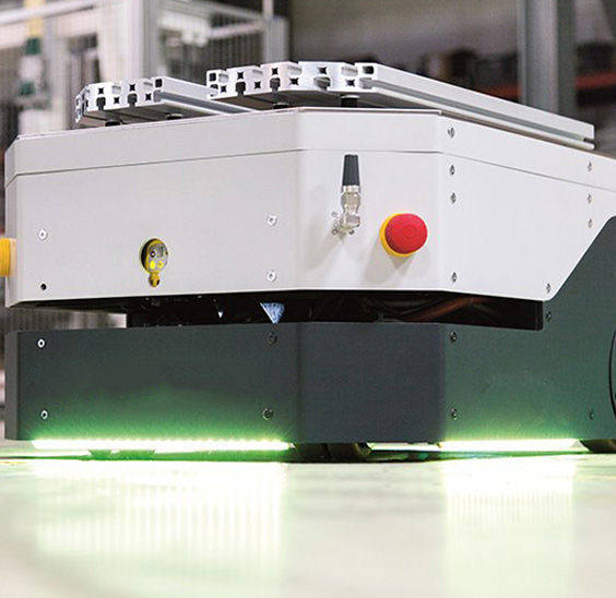
AGV

Automated robots
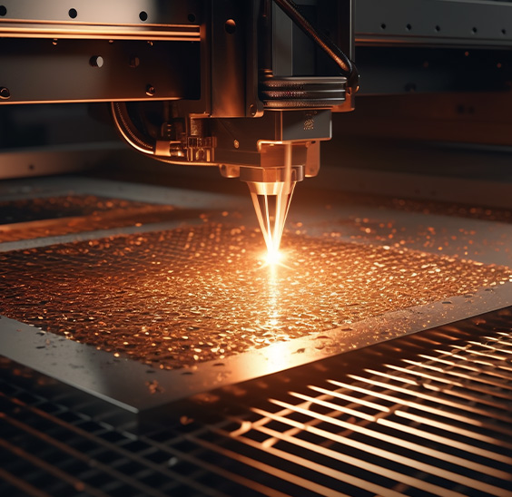
laser cutting

Logistics sorting

Photovoltaic power-station
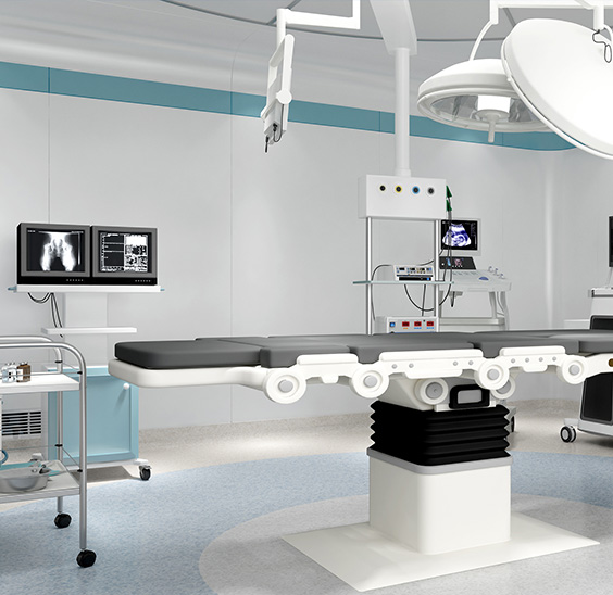
Medical devices
Why Are Brush DC Gear Motors Still the First Choice for High Torque, Low Speed Scenarios?
The Core Value of Brush DC Gear Motors
Brush DC gear motors are the most cost-effective and straightforward solution for applications requiring high torque at low speeds combined with simple speed control. By integrating a brushed DC motor with a mechanical gearbox, these units solve the fundamental problem of DC motors spinning too fast while delivering insufficient torque for most practical mechanical tasks. They remain the dominant choice for designers who need reliable, easily controlled motive power without the complexity or cost of electronic commutation. Their enduring relevance lies in their simplicity, compact footprint, and the unmatched ease of integrating them into basic electrical circuits.
Fundamental Mechanics of Brush DC Gear Motors
To understand the utility of these devices, one must examine the two distinct components that comprise them: the driving motor and the speed-reducing gearbox. The synergy between these two elements is what creates such a versatile actuator.
The Brushed DC Motor Core
At the heart of the system lies the brushed DC motor. This motor generates rotation through electromagnetic induction. When a direct current voltage is applied to the terminals, current flows through the stationary brushes into the rotating commutator, which then directs the current through the armature windings. This current creates a magnetic field that interacts with the static magnetic field generated by the permanent magnets surrounding the armature. The resulting repulsive and attractive forces create torque, causing the shaft to spin. The commutator continuously reverses the current direction in the windings, ensuring continuous rotation. This mechanical commutation makes the motor inherently simple to control; adjusting the voltage directly adjusts the speed, and reversing the polarity reverses the direction.
The Gearbox Reduction Mechanism
While the motor provides the rotational energy, it does so at a speed that is far too high and a torque that is far too low for most practical applications. This is where the gearbox becomes essential. The gearbox operates on the principle of gear reduction, trading speed for torque. A small gear on the motor shaft (the pinion) meshes with a larger gear on the output shaft. Because the larger gear has more teeth, it rotates more slowly than the pinion, but it multiplies the torque applied to it. This relationship is governed by the gear ratio. A high gear ratio results in a significant drop in output speed but a massive multiplication of output torque, enabling the motor to drive heavy loads with minimal electrical input.
Primary Types of Gearboxes Utilized
The performance characteristics of a brush DC gear motor are heavily dictated by the type of gearbox attached to it. Designers must choose between several distinct gear architectures based on the specific demands of their application.
| Gearbox Type | Efficiency | Noise Level | Cost | Typical Application |
|---|---|---|---|---|
| Spur | High | Moderate to High | Low | Consumer electronics, basic actuators |
| Planetary | Very High | Low | High | Robotics, medical devices, precision tools |
| Worm | Low to Moderate | Low | Moderate | Conveyors, elevators, and lifting mechanisms |
Spur Gearboxes
Spur gearboxes are the most common and cost-effective option. They utilize straight-toothed gears mounted on parallel shafts. While they offer excellent efficiency due to the rolling contact between teeth, their straight-tooth design means that teeth mesh entirely at once, resulting in higher operational noise and greater vibration at high speeds. They are best suited for continuous duty applications where noise is not a primary concern.
Planetary Gearboxes
Planetary gearboxes are engineered for high-performance applications. They feature a central "sun" gear, orbiting "planet" gears, and an outer ring gear. This configuration distributes the load across multiple gear teeth simultaneously. Because the load is shared among several points of contact, planetary gearboxes offer exceptional torque density and can handle shock loads far better than spur gears. They also operate with significantly less noise and feature a co-axial input and output shaft, making them highly compact.
Worm Gearboxes
Worm gearboxes consist of a screw-like worm that meshes with a larger worm wheel. Their primary advantage is the right-angle output shaft, which allows for flexible installation in tight spaces. Furthermore, they possess a self-locking characteristic; the geometry of the gears prevents the load from back-driving the motor, which is critical in lifting and holding applications. However, the sliding friction between the worm and the wheel generates heat and significantly reduces mechanical efficiency.
Key Advantages Over Other Motor Systems
Despite the rise of brushless alternatives, brush DC gear motors retain a strong market position due to a distinct set of advantages that make them uniquely suitable for many engineering challenges.
- Unmatched Cost Efficiency: The manufacturing process for brushed motors and standard spur gearboxes is highly mature and inexpensive. They require no electronic controllers for basic operation, drastically reducing the total system bill of materials.
- Simplified Control Architecture: Speed is proportional to voltage, and torque is proportional to current. This linear relationship means that a simple variable resistor or basic pulse-width modulation circuit is sufficient for precise speed adjustment.
- Instantaneous Torque Delivery: Brush DC motors provide maximum torque at zero speed (stall torque), making them ideal for applications that require high starting loads, such as electric jacks or valve actuators.
- Compact and Lightweight Integration: By combining the motor and gearhead into a single unit, the overall length and weight of the drive system are minimized, which is vital in space-constrained assemblies like portable medical devices.
Inherent Limitations and Lifespan Considerations
While highly useful, brush DC gear motors have well-documented limitations that dictate where they should and should not be deployed. Understanding these constraints is critical for avoiding premature system failure.
Brush Wear and Maintenance
The most significant drawback is the mechanical wear of the carbon brushes. Constant friction against the rotating commutator causes the brushes to gradually erode. Eventually, the brushes wear down to the point where they can no longer maintain consistent electrical contact, resulting in motor failure. This limits the operational lifespan of the motor compared to brushless systems, making them unsuitable for continuous 24/7 operation or applications where maintenance access is impossible.
Electrical Noise and EMI
As the brushes make and break contact with the commutator segments, tiny electrical arcs are generated. This arcing produces significant electromagnetic interference (EMI). If the motor is used in proximity to sensitive microcontrollers, radio equipment, or precision sensors, this EMI can cause erratic behavior or signal disruption. Mitigation typically requires the installation of capacitors and varistors directly across the motor terminals, adding to the design complexity.
Thermal Management Challenges
The friction of the brushes and the sliding friction within certain types of gearboxes (especially worm drives) generate substantial heat. In enclosed environments, this heat buildup can degrade the lubricants inside the gearbox, leading to increased wear on the gear teeth and eventual mechanical binding. Designers must account for thermal dissipation to ensure long-term reliability.
Essential Selection Criteria for Optimal Performance
Selecting the correct brush DC gear motor requires a systematic evaluation of the mechanical and electrical demands of the application. Guessing or oversizing can lead to wasted energy, excess heat, or premature failure.
- Determine the Required Output Torque: Calculate the maximum torque needed to start the load and the continuous torque needed to maintain motion. It is standard practice to apply a safety factor to the calculated torque to account for friction and inertia.
- Define the Target Output Speed: Identify the rotational speed required at the output shaft of the gearbox. Ensure that this speed matches the operational requirements without relying on excessive electrical speed reduction, which can cause the motor to stall.
- Calculate the Appropriate Gear Ratio: The gear ratio is derived from the motor's base speed and the desired output speed. A higher ratio provides greater torque multiplication but reduces the output speed proportionally.
- Evaluate Duty Cycle and Thermal Limits: Determine how long the motor will run versus how long it will rest. Continuous duty applications require a motor rated for thermal equilibrium, while intermittent duty allows the use of a smaller motor that operates within safe temperature limits during its rest period.
- Assess Radial and Axial Load Requirements: The output shaft bearings have specific load limits. If the application involves a heavy side load (like a belt drive) or a heavy axial load (like a vertical lift), verify that the gearbox shaft bearings can withstand these forces without premature wear.
Common Industrial and Commercial Applications
The versatility of brush DC gear motors means they are found across a broad spectrum of industries, quietly driving essential mechanisms in both everyday items and specialized industrial equipment.
Automotive Systems
In the automotive sector, these motors are ubiquitous. They are the driving force behind windshield wiper mechanisms, power window regulators, and seat adjusters. The ability to run directly from the vehicle's battery and the simple directional control make them ideal for these intermittent-duty, low-voltage applications.
Home Automation and Smart Devices
The rise of smart homes has increased the demand for motorized actuators. Brush DC gear motors power motorized blinds, smart door locks, and automated pan-tilt mechanisms for security cameras. Their quiet operation (when paired with planetary gears) and low power consumption are highly valued in domestic environments.
Medical and Healthcare Equipment
Medical devices often require precise, low-speed movement with high reliability. These motors are used in hospital bed adjustments, infusion pumps, and mobility scooters. The predictable performance and fail-safe operation of brushed systems are crucial in environments where patient safety is paramount.
Industrial Automation and Robotics
In industrial settings, they are frequently employed in conveyor belt systems, packaging machinery, and autonomous guided vehicles. The gearbox allows the motor to move heavy payloads smoothly, while the simple control interface allows for easy integration with programmable logic controllers.
Maintenance Protocols and Troubleshooting
To maximize the service life of a brush DC gear motor, a proactive approach to maintenance and an understanding of common failure modes are essential.
Lubrication and Gearbox Care
The gearbox is a mechanical system subject to continuous wear. Over time, the grease or oil inside the gearbox can break down, losing its viscosity and ability to protect the gear teeth. Regular re-lubrication with the manufacturer-specified lubricant is critical to prevent premature gear wear and excessive heat generation. Using the wrong type of lubricant can cause chemical incompatibility with seals and internal components, leading to leaks and contamination.
Identifying Brush Degradation
As brushes wear, the carbon dust accumulates inside the motor housing. In some cases, this dust can bridge the gap between commutator segments, causing internal short circuits and drastically reducing performance. Symptoms of worn brushes include intermittent operation, reduced torque output, excessive sparking at the commutator, and a grinding noise. Monitoring the motor's current draw can also indicate brush wear; an increase in no-load current often signals that the brushes are dragging or the commutator is scored.
Addressing Voltage Drops and Connection Issues
A common troubleshooting oversight is blaming the motor for performance issues that actually stem from the power supply. Long wire runs, undersized gauges, or corroded switches can introduce significant voltage drops. If the motor receives less voltage than its rated input, it will fail to produce the required speed and torque. Always measure the voltage directly at the motor terminals while it is under load to ensure the power delivery system is adequate.
Future Outlook in a Brushless-Dominant Era
It is undeniable that brushless DC motors are capturing an increasing share of the market, particularly in high-end applications requiring long life and high efficiency. However, brush DC gear motors are far from obsolete. Their future lies in their role as the pragmatic choice for cost-sensitive, intermittent-duty, and low-complexity applications.
Manufacturers continue to refine the design of brushed motors, utilizing advanced composite brush materials that last longer and produce less EMI, and improving gearbox machining techniques to reduce friction and noise. As long as engineers require a simple, reliable method to convert electrical energy into high-torque mechanical motion without the overhead of electronic drives, the brush DC gear motor will remain an indispensable component in the global engineering toolkit.
Related products
-

This 6W Induction AC Gear Motor is an efficient, compact and reliable small motor suitable for a wide range of industrial and household applications.Motor frame 60mm x 60mm making it easy to install ...
See Details -

The 6W brush DC gbear motor is designed for efficiency and versatility, suitable for various applications. With a compact frame size of 60mm x 60mm, it fits seamlessly into tight spaces. The motor ope...
See Details -

The 10W brush DC gear motor offers high performance and adaptability, for a range of industrial and hobbyist applications. With a frame size of 60mm x 60mm, this motor is designed to fit into confined...
See Details -

The 24V Brushless Gear Motor is a versatile and efficient motor designed for a range of applications. With dimensions ranging from 60mm x 60mm to 104mm x 104mm, this motor can fit into various equipme...
See Details -

The 32mm brushed planetary gear motor is a compact and efficient solution designed for various applications requiring high torque and precise control. With a diameter of 32mm, this motor is ideally su...
See Details -

The 42mm brush planetary gear motor is a versatile and efficient component widely used in various applications requiring precise torque and speed control. With a rated current ranging from 0.7 to 1.1A...
See Details -

The 32mm Brushless Planetary Gear Motor is a high-performance, compact solution ideal for applications requiring efficiency and reliability. Operating at a rated voltage of 24V and consuming 20W of po...
See Details -

The 42mm brushless planetary motor is a high-efficiency motor product that is widely used in various scenarios requiring precision transmission. The rated current of this motor is 1.3A and the rated t...
See Details -

The SPE series gearboxes, flange size range with 40, 60, 80, 120, and 160 models, are designed to provide efficient and robust power transmission solutions. These gearboxes feature a round output flan...
See Details -

The SPF series are with square output flanges, accommodating dimensions from 40mm to 160mm. These flanges are engineered to excel in various industrial applications, offering reliable performance acro...
See Details -

The 52mm brushed planetary gear motor is a compact and efficient solution designed for various applications requiring high torque and precise control. With a diameter of 52mm, this motor is ideally su...
See Details -

The 62mm brush planetary gear motor is a versatile and efficient component widely used in various applications requiring precise torque and speed control. With a rated current ranging from 2.5 to 5.5A...
See Details
CONTACT DETAILS
- TEL: 0086-0571-86951513/86951543
- Fax: 0086-571-86040769
- E-mail: [email protected] / [email protected] / [email protected]
- Office: Hangzhou Saiya Transmisson Equipment Co.,Ltd
- Office Address: Room 2201, Wanyin building, Hangzhou City, Zhejiang Province
- Factory: Zhejiang Saiya Intelligent Manufacturing Co., Ltd.
- Factory Address: No.35 Building , Zhongnan High-tech Yunhe Zhigu Industrial Park, Xinan town, Deqing county, Huzhou city, Zhejiang, China
QUICK LINK
PRODUCT
If You Are Intrested
In Our Products,
Please Consult Us
Copyright © Zhejiang Saiya Intelligent Manufacturing Co., Ltd. All Rights Reserved.
Custom Gear Reduction Motors Suppliers
