 EN
 English
 中文简体
 русский
 Español

Home / News / Industry News / What Is a Planetary Gear Motor? Why Is It Preferred for High-Precision?


Application Industry
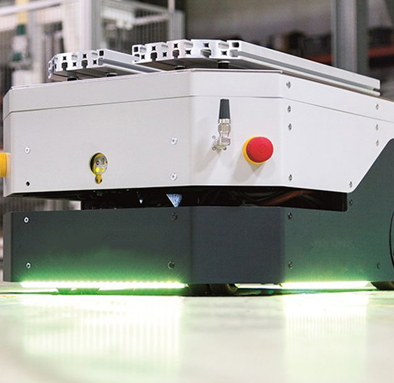
AGV

Automated robots
laser cutting

Logistics sorting

Photovoltaic power-station

Medical devices
What Is a Planetary Gear Motor? Why Is It Preferred for High-Precision?
A planetary gear motor is a compact drive unit that combines an electric motor with a planetary gearbox, distributing torque across multiple planet gears orbiting a central sun gear. For high-precision applications such as robotic joints, AGV drives, and medical equipment, the planetary gear motor is preferred because it delivers high torque density, low backlash, and exceptional torsional rigidity in a package that remains shorter and lighter than equivalent conventional gearmotors.
Engineers responsible for axis drives, indexing tables, or automated guided vehicles often face the same procurement dilemma: the selected gear motor must fit within a tight envelope, hold a repeatable position under fluctuating load, and still meet a cost target. A planetary gear motor answers these constraints with a structural advantage: load is shared simultaneously by three to six planet gears, which reduces individual tooth loading and makes the drivetrain inherently stiffer than a single-stage parallel-shaft or worm gear setup. This article compares the planetary gear motor against conventional alternatives using measurable criteria like backlash, efficiency, torque-to-weight ratio, and service life.
Planetary Gear Motor Definition and Core Working Principle
A planetary gear motor consists of three concentric gear elements: a central sun gear, a set of planet gears mounted on a rotating carrier, and an outer ring gear with internal teeth. The motor shaft drives the sun gear; the planet gears mesh with both the sun gear and the ring gear; the carrier outputs the reduced speed and multiplied torque.
Why load sharing defines the planetary advantage
In a conventional gearmotor, the entire torque transfers through one gear mesh. In a planetary gearbox, the same torque divides across multiple meshing points. For example, a standard single-stage planetary gear motor with four planet gears reduces the load per tooth engagement by roughly 75 percent compared with an equivalent-size parallel-shaft gearmotor. This directly translates to smaller tooth stresses, lower operating temperatures, and longer service life.
- Sun gear: input element, typically driven directly by the motor rotor or through a pinion
- Planet gears: 3 to 6 identical gears that rotate around the sun gear and share the transmitted load
- Ring gear (internal gear): stationary or rotating outer member with internal teeth that meshes with all planet gears simultaneously
- Carrier: the output member that holds the planet gear shafts and transmits the reduced speed to the driven load
The gear ratio for a single-stage planetary set with a fixed ring gear follows this formula:
Ratio = 1 + (Ring Gear Teeth / Sun Gear Teeth)
With a ring gear of 72 teeth and a sun gear of 24 teeth, the ratio becomes 1 + (72/24) = 4.0. Multi-stage planetary gear motors connect two or three sets in series to achieve ratios from 16:1 to 264:1 and beyond, maintaining coaxial input and output shafts throughout.
Core definition
A planetary gear motor is a coaxial gearmotor in which multiple planet gears mesh with a central sun gear and an internal ring gear, dividing transmitted load across several tooth contacts and producing higher torque density and lower backlash than a comparably sized conventional gearmotor.
Why High-Precision Applications Favor the Planetary Gear Motor
High-precision automation tasks demand three mechanical characteristics above all: positional repeatability, torsional rigidity under varying load, and smooth motion at low speeds. The planetary gear motor satisfies all three because every torque path is duplicated three or more times around the circumference, which cancels radial forces and holds a more consistent mesh stiffness through each shaft revolution.
1–3 arcmin
Typical backlash range for precision planetary gearboxes
5–3:1
Weight-to-torque ratio advantage over worm gear motors
95–97%
Single-stage efficiency for precision planetary drive
50%+
Size reduction vs. parallel-shaft gearbox achieving same ratio
Backlash is the measurable angular play between input and output when the direction of rotation reverses. For a standard planetary gear motor, single-stage backlash typically ranges from 10 to 20 arcminutes. Precision grades tighten this to 1 to 3 arcminutes by using ground gear teeth, tighter center distances, and preloaded bearings. For comparison, a conventional worm gearmotor exhibits 5 to 15 arcminutes of backlash after initial wear-in and increases through its service life, whereas a precision planetary set holds its backlash value for thousands of operating hours.
The helical planetary gearbox variant improves on straight-cut planetary gears by engaging teeth gradually along the helix angle instead of along the full face width at once. This reduces noise by 5 to 8 decibels and increases the contact ratio, so torque transfers from one tooth pair to the next without a momentary discontinuity. For servo applications where the reduction ratio and inertia matching determine servo stability, the higher torsional stiffness of a planetary gear motor also raises the resonance frequency of the mechanical system, allowing higher servo gains and sharper positioning response.
Example: a 60 mm planetary gear motor with 20:1 ratio and 3 arcmin backlash maintains positional repeatability of approximately ±0.01° at the output, which converts to less than ±0.17 mm error at a 1 m radius.
Quantified Comparison: Planetary vs. Conventional Gear Motors
To understand where the planetary gear motor justifies its higher initial cost, compare it against worm, parallel-shaft helical, and right-angle hypoid gear motors under identical load requirements. The following table summarizes the differences that most directly affect precision application performance.
| Parameter | Planetary gear motor | Worm gear motor | Parallel-shaft helical gear motor |
| Backlash (single stage) | 1–3 arcmin precision; 10–20 arcmin standard | 5–15 arcmin, increases with wear | 3–10 arcmin depending on grade |
| Efficiency per stage | 95–97% | 70–80% (self-locking ratio around 40:1) | 94–96% |
| Torque density | Highest: load shared across 3–6 planet gears | Lower; sliding friction generates heat | Moderate; single mesh path carries full load |
| Axial space requirement | Compact coaxial design, shortest footprint | Right-angle, increases height | Offsets input and output shafts, longer axial length |
| Noise under 3000 rpm input | 50–62 dB, helical variants quieter | 65–75 dB depending on sliding velocity | 60–70 dB |
| Servo compatibility | Low inertia mismatch, high stiffness, low backlash | Poor due to backlash fluctuation and friction | Acceptable with precision gear grades |
These numbers lead to a clear selection conclusion: the planetary gear motor wins whenever the application demands high cycle rates, reversing motion, tight positional accuracy, or long duty life in a compact installation envelope. When the load is unidirectional, operates at constant speed, and cost per unit is the dominant factor, a helical or worm solution may still be appropriate.
Structural Design Factors That Control Precision and Service Life
A precision planetary gear motor is not simply a standard unit with tighter tolerances. The design choices made by the manufacturer determine whether the gearbox will hold its accuracy for its intended design life, especially in equipment that runs three shifts or operates in reversing duty cycles.
Gear geometry and tooth finishing
The type of gear cutting and finishing sets the upper limit of achievable precision. Hobbing or shaping produces gears with a tooth quality typically around DIN 7–8. Hard finishing, including profile grinding, upgrades quality to DIN 5–6 and reduces backlash consistency from gear to gear. Gear material selection also separates the tiers: case-hardened alloy steel with a surface hardness of 58–62 HRC resists pitting and wear far better than through-hardened carbon steel at 45–50 HRC. In a planetary gear motor, the planet gears are the most stressed components because they roll around the sun gear and export load through their own bearings. Their bearing arrangement, needle roller versus sleeve, dictates how accurately the carrier maintains center distances under full torque.
Housing rigidity and bearing support
Torque reaction in a planetary gear motor flows through the ring gear into the housing. A thin-walled aluminum housing deflects measurably under rated torque, increasing effective backlash and reducing positional stability. Precision planetary gearboxes therefore use thicker housing walls, sometimes with a steel ring-gear insert, and support the output shaft with a pair of preloaded ball bearings rather than a single bearing. This contributes directly to a higher stiffness rating expressed in Newton-meters per arcminute of torsional deflection. A practical check for any supplier is to request their stiffness value and compare it against the peak torque of your application.
Quality indicators in a precision planetary gear motor
- Output torque rating stated at input speeds above 3000 rpm without de-rating
- Backlash specified per stage, not averaged over the whole unit
- Lubricant type and fill volume stated for the operating temperature range
- Radial and axial output shaft load capacities published separately
- Efficiency chart across speed and torque range available
Design shortcuts that shorten service life
- Plastic ring gear or plastic planet gears rated at "peak" torque only
- Single bearing output support with no preload
- Heat-treated gears below 50 HRC surface hardness
- No stated backlash tolerance, only a nominal value
- Lubricated for life without dielectric strength for inverter-fed motors
The operating temperature inside the gear-stage of a planetary gear motor directly follows from the efficiency loss multiplied by the transmitted power. A 100 W planetary gear motor with 96 percent single-stage efficiency dissipates about 4 watts of heat; a worm drive at 80 percent efficiency dissipates 20 watts for the same output. That difference explains why planetary gear motors run cooler, preserve grease properties longer, and need maintenance less frequently in continuous production environments.
Inertia Matching and Servo Loop Compatibility in a Planetary Gear Motor
High-precision applications usually mean servo or stepper control, and a servo-driven planetary gear motor must be evaluated not only as a mechanical reducer but also as part of the tuning loop. Inertia matching ranks among the most common selection errors: a gearbox ratio that is too low leaves the motor inertia much lower than the reflected load inertia, causing overshoot; a ratio that is too high reduces achievable axis speed and responsiveness.
The reflected load inertia at the motor shaft decreases by the square of the gearbox ratio. Doubling the planetary gear motor ratio from 5:1 to 10:1 reduces the reflected inertia by a factor of four. This matters in applications such as robotic wrist joints and indexing turrets where quick start-stop cycles require the drive to settle quickly. A planetary gearbox offers the short axial length and low internal inertia that help meet this requirement without adding a separate inertia matching device.
Torque ripple is the second parameter that directly influences positioning quality. A planetary gear motor with precision-ground gears and a high contact ratio produces smooth rotation even under load, which allows the servo drive to run with lower gain margins and avoid audible singing or vibration. In contrast, a low-cost planetary unit with hobbed gears and wide backlash creates measurable torque ripple at each tooth engagement frequency, forcing the commissioning engineer to reduce servo gains or add a low-pass filter, both of which degrade settling time.
Selecting a Planetary Gear Motor: Practical Parameters and Procurement Criteria
When you evaluate a planetary gear motor for a precision application, the process reduces to four quantifiable checks: torque at the required speed, backlash and stiffness, service factor relative to your duty cycle, and environmental compatibility. Each parameter affects the motor frame size, gearbox ratio, and bearing layout you need.
Torque: nominal versus peak rating
Nominal torque ratings in planetary gearmotors are defined as the torque the unit can run continuously without exceeding a specific temperature rise, usually 55 to 65°C above ambient. Peak torque ratings represent short-duration capability, normally 1.5 to 2 times the nominal rating for a few seconds, and must not be used as the basis for continuous operation. In high-cycle pick-and-place equipment, the RMS torque over the cycle must stay below the nominal rating, and the peak torque in each cycle should not exceed the manufacturer's stated peaktorque multiplied by the service factor. A planetary gear motor constructed with case-hardened gears and large bearings provides enough reserve for these transient peaks without reducing fatigue life.
Measuring and specifying backlash
Backlash for a planetary gear motor is specified in arcminutes one direction to the other, measured with a defined input torque to remove gear tooth deflection. Precision products document this value per stage and distinguish it from lost motion measured under increasing load, which includes gear deflection in addition to clearance. If your application indexes through a reversing cycle, select a backlash value below, not at, the maximum permissible error. For example, a positioning tolerance of 0.2 degrees at the output recommends a gearmotor with no more than approximately 6 arcminutes of total backlash, leaving margin for load deflection and servo error.
1
Define the RMS and peak torque from the actual duty cycle, not the motor nameplate rating.
2
Calculate the minimum ratio that keeps the reflected load inertia between one and five times the motor inertia.
3
Determine the permissible total backlash at the output, then allocate no more than half of that to the gearbox.
4
Check radial and axial load ratings against the actual overhung load from belts, gears, or direct coupling.
5
Verify speed reduction at rated torque stays within the thermal limit of the housing.
6
Confirm mounting orientation since lifetime lubrication and bearing preload changes with shaft direction.
Real-World Applications Where Planetary Gear Motors Prove Their Value
The functional advantages of a planetary gear motor translate into measurable performance in several high-precision fields. Automation builders select these drives for robotic, AGV, packaging, semiconductor handling, and medical equipment because the reliability of the drivetrain directly affects the uptime and throughput of the final machine.
Robotic arms and gantry systems
Robot joints require a low-speed, high-torque output with minimal backlash at every load condition. A planar gear motor with single-stage ratio of 8:1 to 10:1 and backlash below 5 arcminutes provides the positional repeatability that maintains the tool center point accuracy over thousands of operations. The coaxial and short-axial form factor also simplifies the mechanical integration into the elbow and wrist joints where space is severely restricted.
AGV drive and steering axes
AGV systems run through repeated start, stop, and reversing cycles while carrying payloads that vary with each mission. The planetary gear set handles the high dynamic shocks when the vehicle drives over uneven floors, and its high efficiency maximizes battery run time. The careful inertia matching possible with a planetary gearbox also prevents the wheel axle from oscillating when the vehicle switches between forward and reverse motion at high frequency.
Medical scanning and positioning equipment
Medical devices operate at lower speeds but demand very low noise and high positional consistency. A planetary gear motor with helical planetary gears reduces the noise from the reduction stage to levels compatible with diagnostic rooms where the ambient sound limit is strictly enforced. The tighter backlash of a precision planetary set also prevents the image artifact that can occur when a scanning axis passes through zero torque direction change.
Cost Considerations and Lifetime Cost Analysis
Choosing a planetary gear motor often increases the initial component cost compared with a parallel-shaft or worm gearmotor, but the relevant comparison is total cost of ownership over the machine's life, including downtime and replacement parts. The following scenarios illustrate where the planetary drive wins economically.
| Cost item | Planetary gear motor | Worm gear motor |
| Initial purchase cost | $85 | $55 |
| Replacement units per year (duty class S1) | 0.2 | 0.8 |
| Consumed energy over five years (50% load, 0.10/kWh) | $320 | $420 |
| Estimated maintenance labor over five years | $60 | $180 |
| Total five-year cost | $505 | $735 |
This simplified example assumes both products meet the performance requirements, which is usually true for non-critical constant-speed applications. For high-precision, high-cycle applications, the worm drive would fail the positional accuracy requirement regardless of lifetime cost, making the planetary gear motor the only responsible choice.
Interpreting a Planetary Gear Motor Data Sheet
A manufacturer's data sheet for a planetary gear motor contains the parameters that determine whether the unit suits your application. You need to understand which numbers are rated values, which are limit values, and which ones depend on speed and temperature.
- Rated torque: the torque the unit can deliver continuously at a specified input speed and ambient temperature, typically at 25°C
- Backlash: the average or maximum angular play measured without load, expressed in arcminutes
- Torsional stiffness: the torque required to produce one arcminute of torsional deflection at the output, expressed in N·m/arcmin
- Reduction ratio: the exact ratio of input speed to output speed, which can differ slightly from the rounded ratio printed on the label
- Efficiency: the mechanical efficiency per stage or for the whole gearunit, valid in one direction unless specified
When comparing planetary gear motor options from different manufacturers, verify that the rated torque is based on the same operating speed, ambient temperature, and duty cycle. A unit rated at ambient 25°C cannot deliver the same torque at 60°C without acceleration of seal and grease aging. Always request the efficiency curve over the full speed range instead of relying on the single peak value published on the datasheet.
Maintenance and Failure Modes in Planetary Gear Motors
A planetary gear motor with correctly selected size and ratio delivers decades of trouble-free service when operated within its ratings, but application mistakes produce distinct failure patterns. Understanding the failure signatures helps you identify the root cause before replacing the unit.
Wear patterns and their causes
The most common mode in over-loaded planetary gear motor is tooth pitting on the planet gears, which appears as small craters on the tooth flank under microscopic inspection. This occurs when the Hertzian contact stress exceeds the material endurance limit and is accelerated when the lubricant thins at elevated temperature. Another common mode is a brinelling in the planet gear bearing race, which produces continuous periodic noise at the rotational frequency of the carrier. In both cases, the fix involves either a larger gearbox frame or lower torque requirement rather than a replacement of the same model.
Backlash growth over life
Precision planetary gear motor with hardened and ground gears exhibits minimal backlash increase because hardened surfaces resist wear. Standard-grade units with soft gears can double their backlash within the first thousand hours if operated at high torque and in reversing duty. For high-precision applications, the cost premium for a precision planetary gearbox with case-hardened and ground gears is justified by keeping actual positioning drift under control.
Frequently Asked Questions about Planetary Gear Motors
What is the difference between a planetary gear motor and a regular gear motor?
A planetary gear motor distributes load across multiple planet gears between a sun gear and an internal ring gear, allowing higher torque density, lower backlash, and shorter axial length. A regular gear motor, such as a parallel-shaft helical or worm unit, transfers torque through a single mesh path or sliding contact, producing a larger and often less efficient drive.
What is the typical backlash in a precision planetary gear motor?
Precision planetary gear motors achieve 1 to 3 arcminutes of backlash per stage when equipped with ground gears, preloaded bearings, and tight center distances. Standard commercial grades typically show 10 to 20 arcminutes, which is acceptable for general machinery but insufficient for positioning axes.
Can a planetary gear motor be used in a servo loop?
Yes, and it is often the recommended gearbox type for servo applications because of its low inertia, high torsional stiffness, and low backlash. The gearbox ratio must be chosen to match the reflected load inertia to the servo motor inertia, usually between one and five times the motor inertia.
Why is a planetary gear motor more efficient than a worm gear motor?
Worm gear motors lose a significant portion of energy through sliding friction between worm and wheel, typically 15 to 25 percent per stage. A planetary gear motor transmits torque through rolling contact between gear teeth, achieving 95 to 97 percent efficiency per stage, which reduces heat and operating cost.
Related products
-
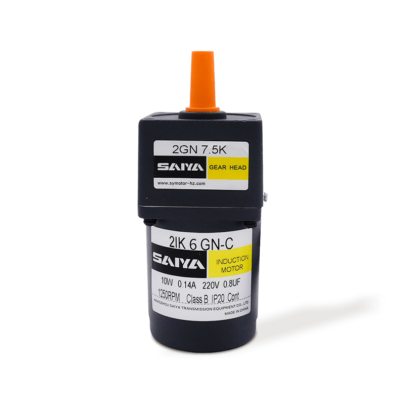
This 6W Induction AC Gear Motor is an efficient, compact and reliable small motor suitable for a wide range of industrial and household applications.Motor frame 60mm x 60mm making it easy to install ...
See Details -
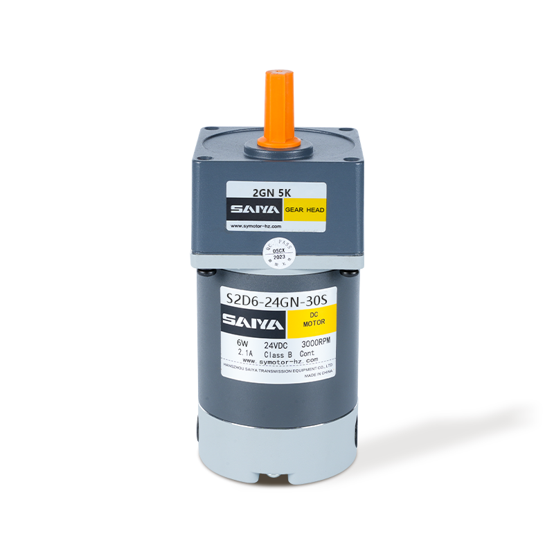
The 6W brush DC gbear motor is designed for efficiency and versatility, suitable for various applications. With a compact frame size of 60mm x 60mm, it fits seamlessly into tight spaces. The motor ope...
See Details -
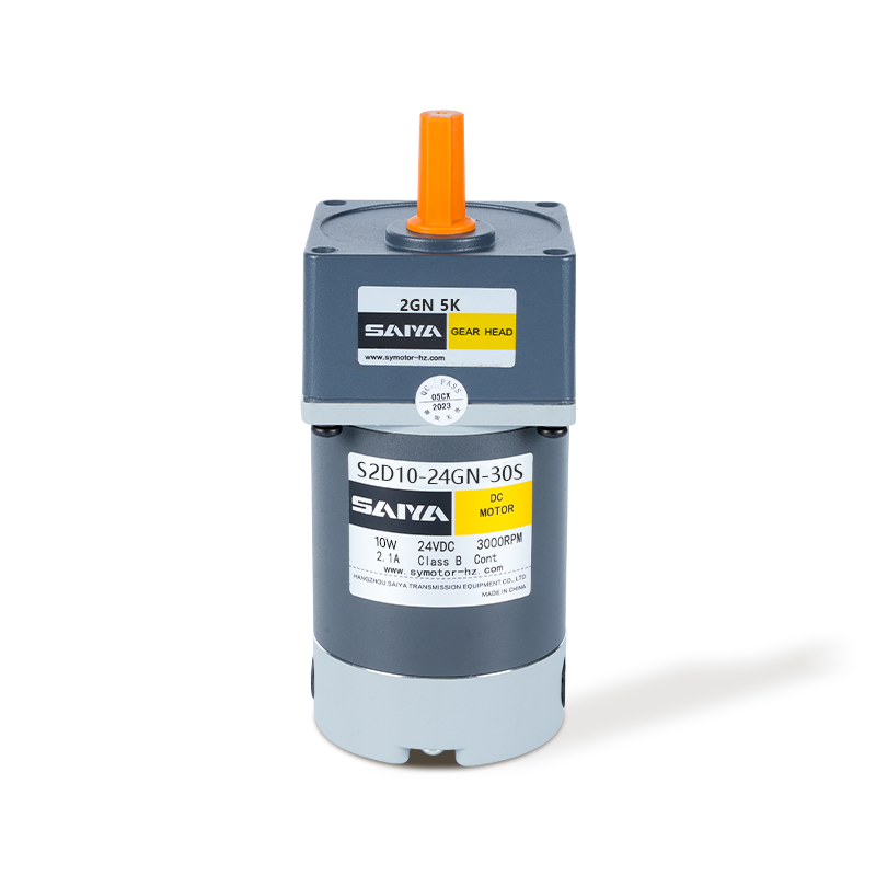
The 10W brush DC gear motor offers high performance and adaptability, for a range of industrial and hobbyist applications. With a frame size of 60mm x 60mm, this motor is designed to fit into confined...
See Details -
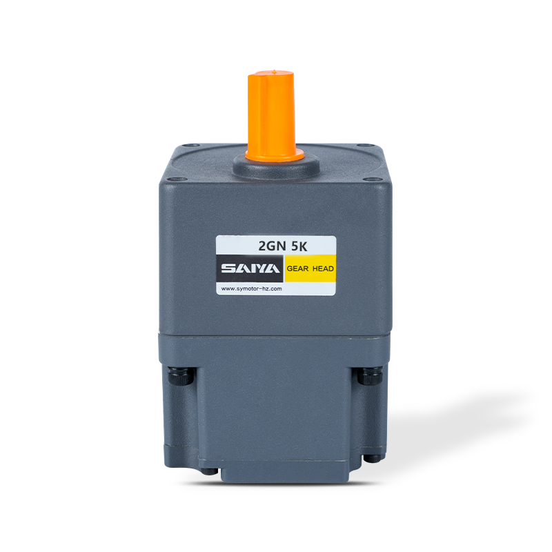
The 24V Brushless Gear Motor is a versatile and efficient motor designed for a range of applications. With dimensions ranging from 60mm x 60mm to 104mm x 104mm, this motor can fit into various equipme...
See Details -
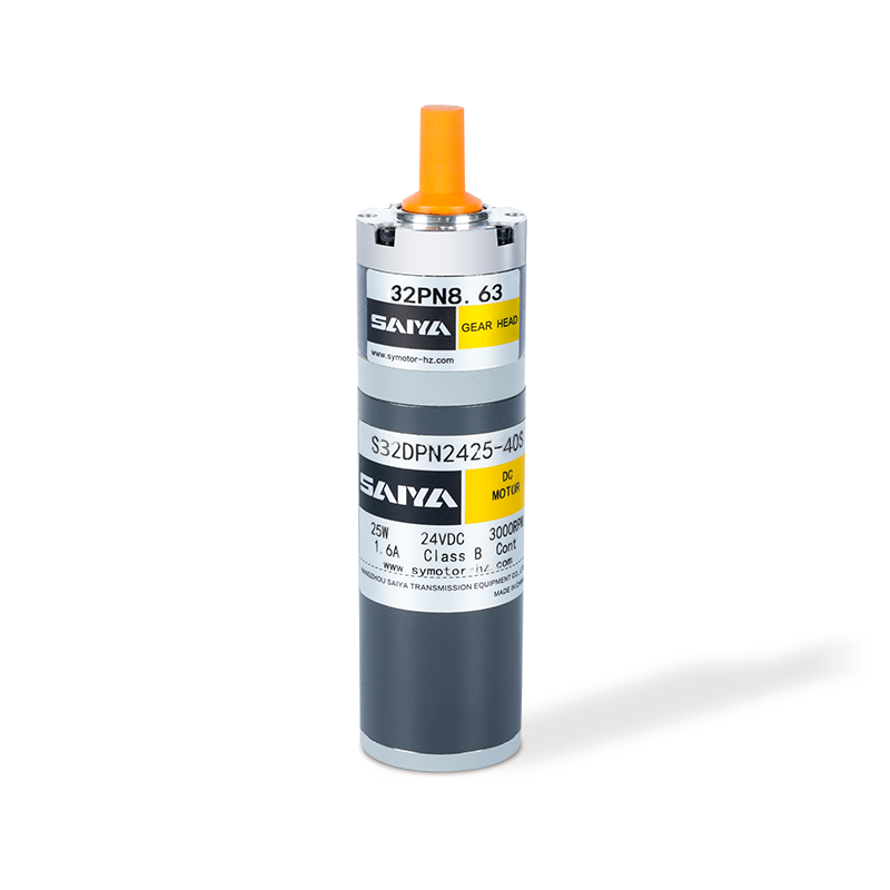
The 32mm brushed planetary gear motor is a compact and efficient solution designed for various applications requiring high torque and precise control. With a diameter of 32mm, this motor is ideally su...
See Details -
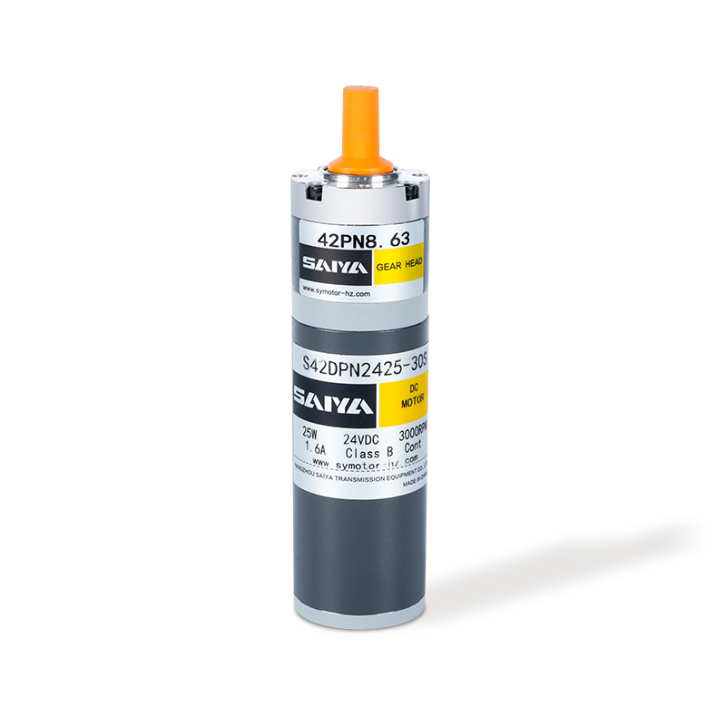
The 42mm brush planetary gear motor is a versatile and efficient component widely used in various applications requiring precise torque and speed control. With a rated current ranging from 0.7 to 1.1A...
See Details -
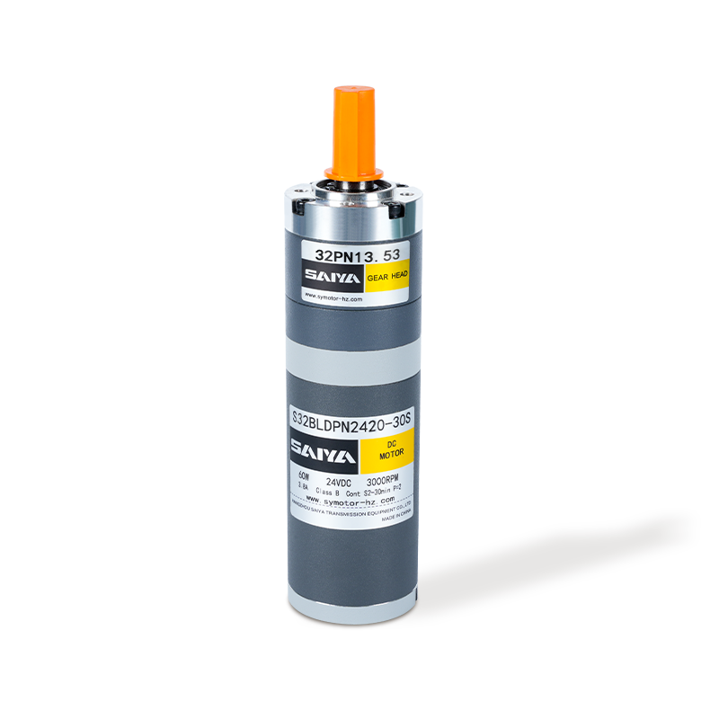
The 32mm Brushless Planetary Gear Motor is a high-performance, compact solution ideal for applications requiring efficiency and reliability. Operating at a rated voltage of 24V and consuming 20W of po...
See Details -
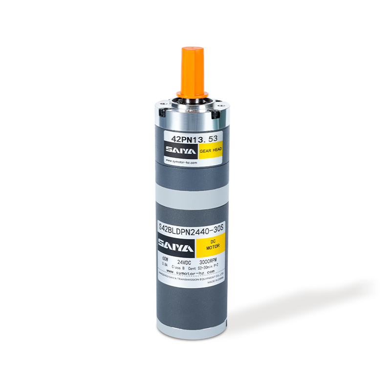
The 42mm brushless planetary motor is a high-efficiency motor product that is widely used in various scenarios requiring precision transmission. The rated current of this motor is 1.3A and the rated t...
See Details -
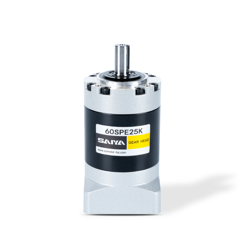
The SPE series gearboxes, flange size range with 40, 60, 80, 120, and 160 models, are designed to provide efficient and robust power transmission solutions. These gearboxes feature a round output flan...
See Details -
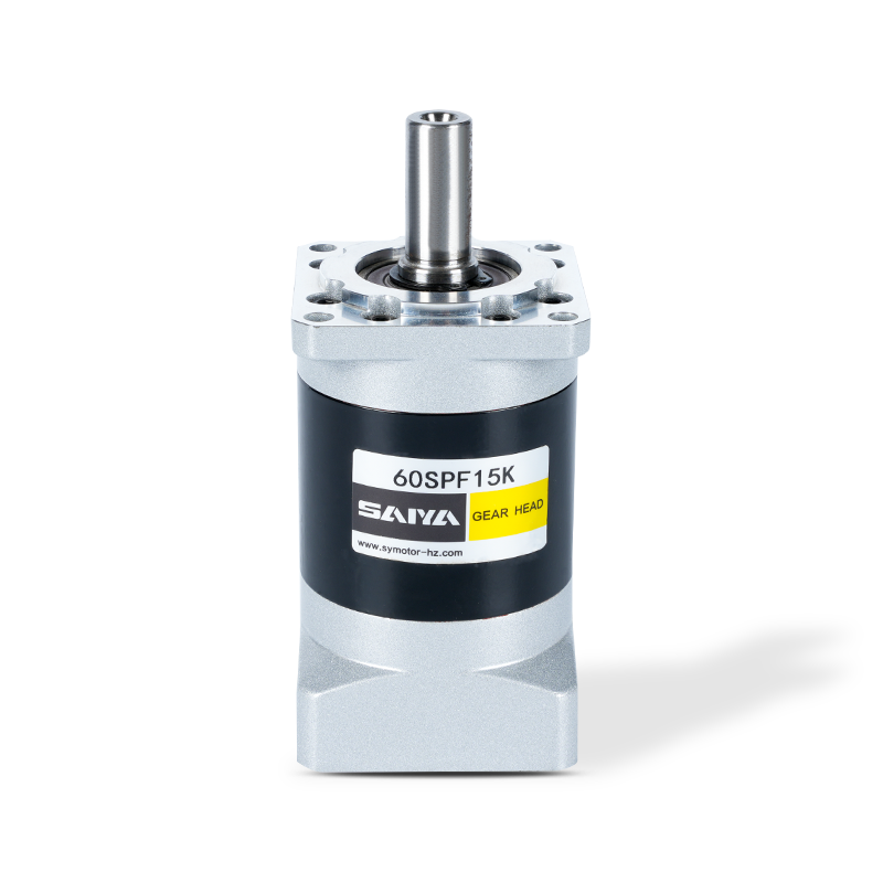
The SPF series are with square output flanges, accommodating dimensions from 40mm to 160mm. These flanges are engineered to excel in various industrial applications, offering reliable performance acro...
See Details -
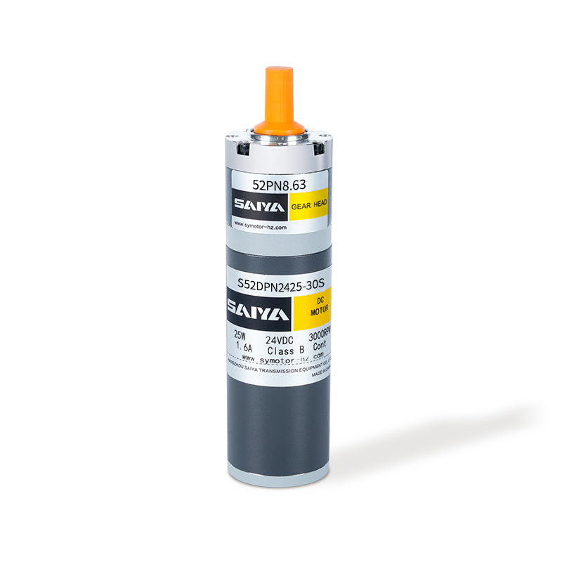
The 52mm brushed planetary gear motor is a compact and efficient solution designed for various applications requiring high torque and precise control. With a diameter of 52mm, this motor is ideally su...
See Details -
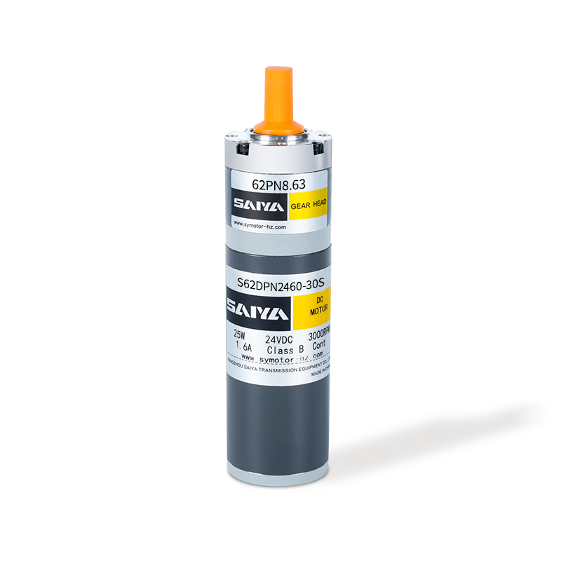
The 62mm brush planetary gear motor is a versatile and efficient component widely used in various applications requiring precise torque and speed control. With a rated current ranging from 2.5 to 5.5A...
See Details
CONTACT DETAILS
- TEL: 0086-0571-86951513/86951543
- Fax: 0086-571-86040769
- E-mail: [email protected] / [email protected] / [email protected]
- Office: Hangzhou Saiya Transmisson Equipment Co.,Ltd
- Office Address: Room 2201, Wanyin building, Hangzhou City, Zhejiang Province
- Factory: Zhejiang Saiya Intelligent Manufacturing Co., Ltd.
- Factory Address: No.35 Building , Zhongnan High-tech Yunhe Zhigu Industrial Park, Xinan town, Deqing county, Huzhou city, Zhejiang, China
QUICK LINK
PRODUCT
If You Are Intrested
In Our Products,
Please Consult Us
Copyright © Zhejiang Saiya Intelligent Manufacturing Co., Ltd. All Rights Reserved.
Custom Gear Reduction Motors Suppliers
