 EN
 English
 中文简体
 русский
 Español

Home / News / Industry News / How to Choose the Right DC Gear Motor for Battery-Powered Applications


Application Industry
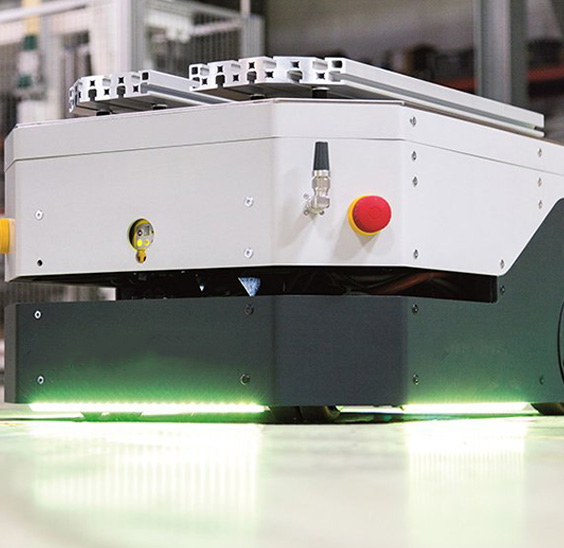
AGV

Automated robots

laser cutting

Logistics sorting

Photovoltaic power-station

Medical devices
How to Choose the Right DC Gear Motor for Battery-Powered Applications
An automated guided vehicle that has to finish an eight-hour shift on a 48 V pack is a different engineering problem from a portable medical pump that cycles for a few minutes a day. Choosing the right DC gear motor for battery-powered applications decides run time, stall margin, and service life before any software tuning can help. A DC gear motor combines a permanent-magnet DC motor with an integral reduction gearbox that increases output torque and reduces output speed by a fixed ratio; in battery equipment, the same design is available in brushed and brushless versions across 12 V, 24 V, and 48 V windings.
How to Choose the Right DC Gear Motor Torque and Speed First
Output torque and speed define the motor, not catalog wattage. Measure the load the actuator actually moves: running torque at the wheel or spindle, breakaway torque at startup, and the top speed the machine needs. The gearbox ratio then relates those values to the motor shaft. When the load calls for 12 Nm at 200 rpm and the reduction stage is 10:1, the motor must hold 1.2 Nm at 2000 rpm, which is roughly 250 W of mechanical output before controller losses.
Add 15-20 percent headroom to that first estimate for winding resistance, battery sag, and gearbox friction. The practical rule is P = T x n / 9.55, where P is mechanical output in watts, T is torque in Nm, and n is speed in rpm. For a worked example with different load cases, see our step-by-step guide to torque calculation for gear motors.
Match the DC Gear Motor Winding to Battery Voltage
Battery voltage decides which motor families are eligible before any performance comparison starts. A motor wound for 48 V run on a 24 V pack delivers roughly one quarter of rated power because power scales with the square of the voltage ratio. Fix the pack voltage first: 12 V for light portable tools, 24 V for compact AGV drives and lifting columns, 48 V for higher-power logistics platforms where current savings matter most.
| Architecture | Current at 250 W | Motor families | Wiring impact |
| 12 V | 20.8 A | Brushed 90-120 W | Heavy conductors, 30 A fusing |
| 24 V | 10.4 A | Brushed 90-250 W, BLDC | Standard cable, 20-50 A BMS |
| 48 V | 5.2 A | BLDC 120 W and above | Thin conductors, fast charging |
Every 250 W of continuous load costs about 5.2 A on a 48 V bus, 10.4 A on a 24 V bus, and 20.8 A on a 12 V bus. Low-voltage wiring gets expensive quickly.
After the pack voltage is fixed, check the winding against the full discharge curve. A 24 V lithium pack can sit below 21 V at 20% state of charge under load, and the winding must still produce useful torque at that voltage. Our low-voltage brushless gear motor family is wound for exactly this operating envelope.
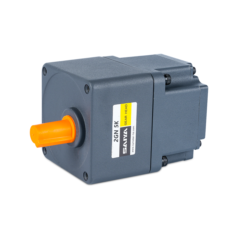 24V Brushless DC Gear Motor for Low-Voltage Battery ApplicationsThis 24V brushless gear motor is wound to maintain torque across a lithium pack's full discharge curve, suiting battery-driven systems. Rated 25-400W at 3000 RPM with 0.08 N·m torque, it delivers 85-92% efficiency, extending run time compared to brushed alternatives.View Product →
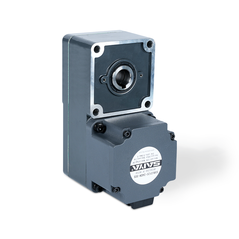 48V Brushless Gear Motor with Higher Torque RangeFor higher-voltage battery packs, this 48V brushless gear motor offers 0.2-1.27 N·m torque across 25-400W, maintaining efficiency over the operating range. Its brushless design reduces maintenance and noise, ideal for automation and electric vehicle drivetrains.View Product →
Brushed vs Brushless DC Gear Motors: Where Battery Run Time Is Decided
Brushless DC gear motors return more energy from the same battery because their efficiency holds across the operating range. A brushed DC gear motor typically peaks between 70% and 80%, while a brushless design reaches 85-92% in the same frame size. On a 100 Wh pack, a 90% efficient motor delivers about 90 Wh to the load; a 72% efficient brushed motor delivers 72 Wh, an 18-20% run time gap before gearing losses are included.
Brushed DC gear motor
Lower controller cost and simple reversing make brushed units attractive for short-cycle battery tools. Brushes wear, generate dust, and efficiency falls hard at partial load.
Brushless DC gear motor
Higher efficiency, longer service life, lower EMI and quiet sensorless operation fit continuous, battery-powered motion. Upfront cost is higher and a controller is mandatory.
Typical efficiency trends for 40-120 W DC gear motors in the 24-48 V range.
In battery-powered motion, efficiency is not a datasheet reward. A 15-point efficiency gap becomes roughly 30% more heat inside the enclosure and 15-20% less run time at the same load.
Choose the Gearbox by Load Type and Shock Conditions
The reduction stage converts a fast, low-torque motor into the torque the application needs, but the gearbox type decides how much of that torque survives and how long the stage lasts. Planetary gearboxes distribute the load across several planet gears, which increases torque density, reduces backlash, and improves radial-load capacity compared with a parallel spur stage of the same diameter. Right-angle planetary units save space in steering and lifting assemblies but add a bevel or worm stage with its own efficiency cost.
| Gearbox type | Backlash | Radial load | Efficiency per stage | Best battery use |
| Spur, parallel | 0.5-1.0 degree | Lower | 97-98% | Light actuators, low shock |
| Planetary | 0.3-0.8 degree | Higher | 95-97% | AGV drive, lifting, shock |
| Right angle | 0.5-1.5 degree | Medium | 90-95% | Compact steering, elevators |
Battery-powered robots and AGVs accumulate thousands of start-stop and reversing cycles per shift, so shock capacity matters more than peak datasheet torque. A planetary gearbox with backlash under 0.8 degree also keeps positioning repeatable when the motor runs in speed or position control. A compact 42 mm brushless planetary gear motor is a practical starting point for medium-duty battery robots.
In battery robotics, gearbox shock rating decides service life more than the motor peak torque number. A planetary stage with backlash below 0.8 degree preserves positioning repeatability over thousands of cycles.
 42mm Brushless Planetary Gear Motor with Wide Reduction RatiosThis compact 42mm brushless planetary motor provides reduction ratios from 3.7 to 307.54, enabling precise speed and torque control for robots and AGVs. With 0.048 N·m rated torque and low backlash, it suits start-stop cycles and position-controlled motion.View Product →
Verify Duty Cycle, Temperature Rise, and the Real Ambient
A motor rated for S1 continuous duty at 40°C ambient will derate inside a sealed battery enclosure that reaches 55°C. Most battery-driven actuators run in S2 short-time or S3 intermittent duty, and the rating defines how long full torque can be held before the winding exceeds the insulation class limit. Confirm the insulation class, typically Class F at 155°C, and the permitted temperature rise on the datasheet.
A permanent-magnet DC motor runs at a no-load speed proportional to voltage and develops stall torque proportional to current. Battery sag rewrites both values in real time.
When a 24 V pack falls to 21 V at 20% state of charge, speed and available torque drop roughly 12%. Specify the motor for the low end of the discharge curve rather than the resting voltage, and record locked-rotor current as well as rated current because both drive connector and fuse sizing.
85-92%Typical brushless peak efficiency
20.8 to 5.2 ACurrent for 250 W from 12 V to 48 V
10,000-20,000 hBrushless service life in continuous duty
10:1Gear ratio example, 0.3 to 3.0 Nm output
A Battery-Powered Selection Checklist for DC Gear Motors
Use this sequence when comparing quotes or reviewing a supplier proposal. It catches most sizing and compatibility errors before prototyping.
- Convert running load torque and top speed to motor shaft values using the gearbox ratio, then add 15-20% headroom.
- Lock the battery architecture and confirm the motor winding matches the low end of the discharge curve.
- Choose brushless when run time, noise, or service life drives the spec; choose brushed when first cost and a simple controller matter more.
- Select a gearbox that carries shock and radial loads without forcing a larger motor.
- Verify duty cycle against the motor thermal class at the actual enclosure ambient.
If a requirement is still unclear after these checks, share the load profile and battery specification with our engineering team for a motor specification review before tooling or sampling.
Battery-Powered DC Gear Motor FAQ
What is the most common mistake in DC gear motor selection for battery equipment?
Sizing by peak torque instead of continuous load. A brief start-up peak can be handled by thermal mass and a slightly larger gearbox, but continuous operation near stall torque will trip thermal limits, shorten brush life, and drain the battery faster than the run-time estimate suggests.
How much longer will a brushless DC gear motor run on the same battery?
Run time scales almost directly with average efficiency. At 85-92% brushless versus 70-80% brushed, expect 12-20% more operating time from the same pack, plus less waste heat inside the sealed battery enclosure.
Should I choose a 24 V or 48 V motor for an AGV drive?
Use 24 V for compact AGVs up to about 250 W where the BMS and cabling stay small. Move to 48 V above roughly 250 W to halve current, shrink conductor size, and simplify higher-power battery management.
Do I need a planetary gearbox for a battery-powered application?
Planetary stages are the safer default for start-stop, reversing, and shock-loaded battery applications because they distribute load across multiple gears. If the duty is smooth and continuous, a parallel shaft gearmotor at a lower ratio can be more cost-effective.
Related products
-
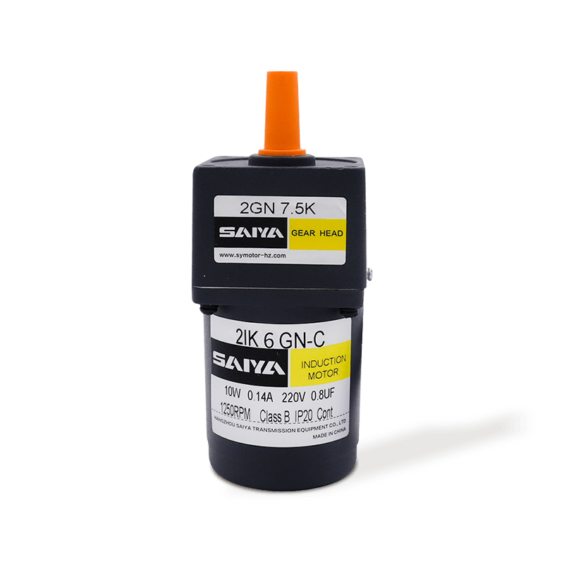
This 6W Induction AC Gear Motor is an efficient, compact and reliable small motor suitable for a wide range of industrial and household applications.Motor frame 60mm x 60mm making it easy to install ...
See Details -
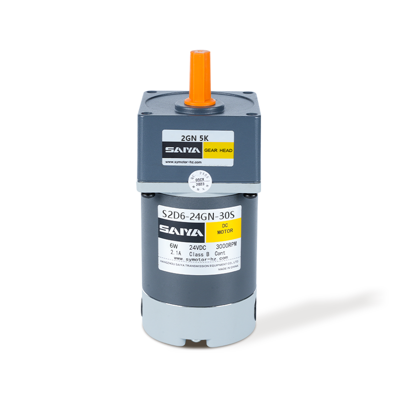
The 6W brush DC gbear motor is designed for efficiency and versatility, suitable for various applications. With a compact frame size of 60mm x 60mm, it fits seamlessly into tight spaces. The motor ope...
See Details -
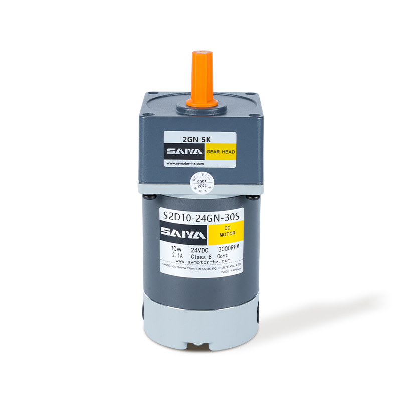
The 10W brush DC gear motor offers high performance and adaptability, for a range of industrial and hobbyist applications. With a frame size of 60mm x 60mm, this motor is designed to fit into confined...
See Details -
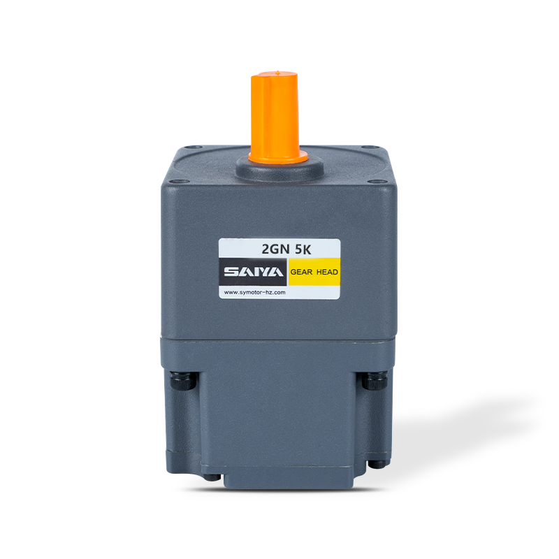
The 24V Brushless Gear Motor is a versatile and efficient motor designed for a range of applications. With dimensions ranging from 60mm x 60mm to 104mm x 104mm, this motor can fit into various equipme...
See Details -
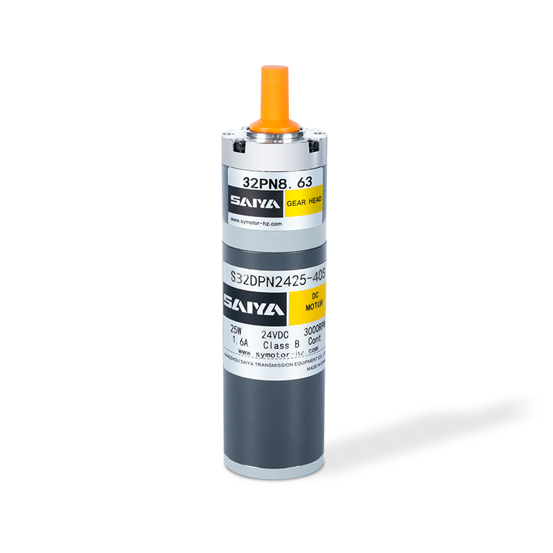
The 32mm brushed planetary gear motor is a compact and efficient solution designed for various applications requiring high torque and precise control. With a diameter of 32mm, this motor is ideally su...
See Details -
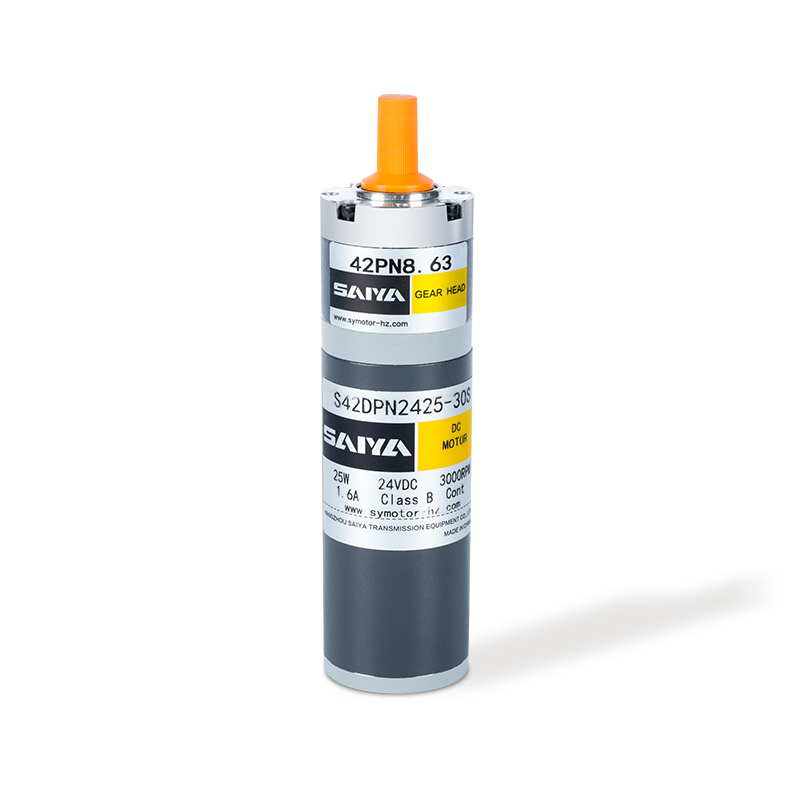
The 42mm brush planetary gear motor is a versatile and efficient component widely used in various applications requiring precise torque and speed control. With a rated current ranging from 0.7 to 1.1A...
See Details -
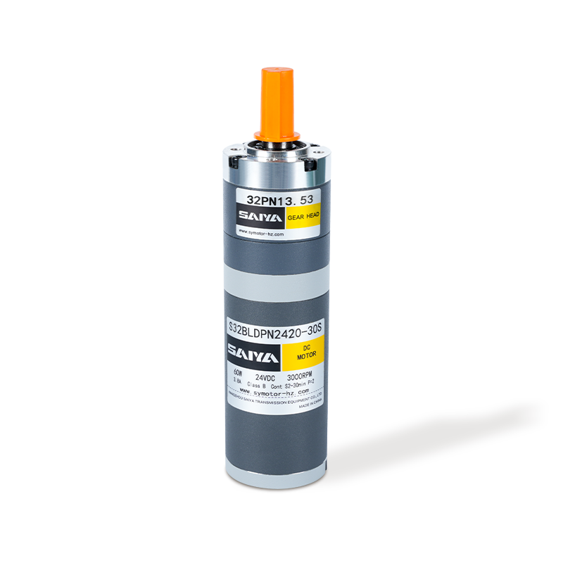
The 32mm Brushless Planetary Gear Motor is a high-performance, compact solution ideal for applications requiring efficiency and reliability. Operating at a rated voltage of 24V and consuming 20W of po...
See Details -
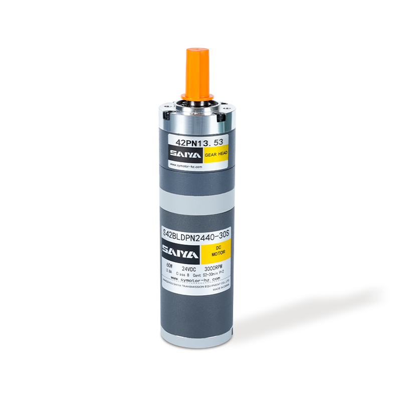
The 42mm brushless planetary motor is a high-efficiency motor product that is widely used in various scenarios requiring precision transmission. The rated current of this motor is 1.3A and the rated t...
See Details -
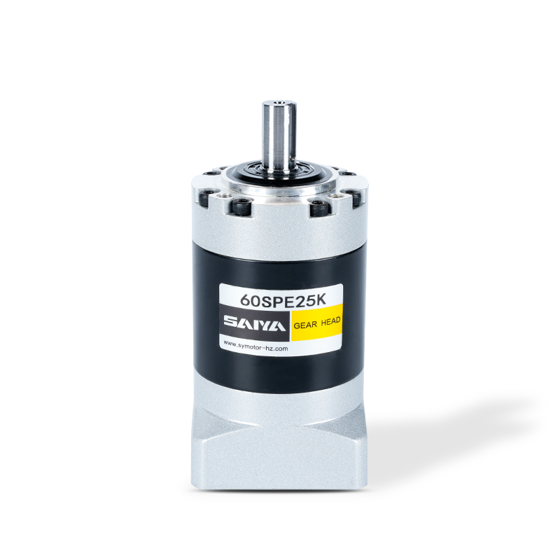
The SPE series gearboxes, flange size range with 40, 60, 80, 120, and 160 models, are designed to provide efficient and robust power transmission solutions. These gearboxes feature a round output flan...
See Details -
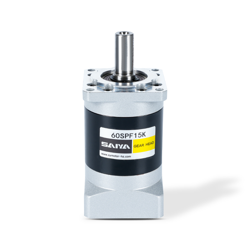
The SPF series are with square output flanges, accommodating dimensions from 40mm to 160mm. These flanges are engineered to excel in various industrial applications, offering reliable performance acro...
See Details -
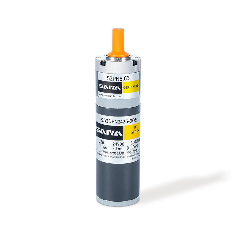
The 52mm brushed planetary gear motor is a compact and efficient solution designed for various applications requiring high torque and precise control. With a diameter of 52mm, this motor is ideally su...
See Details -
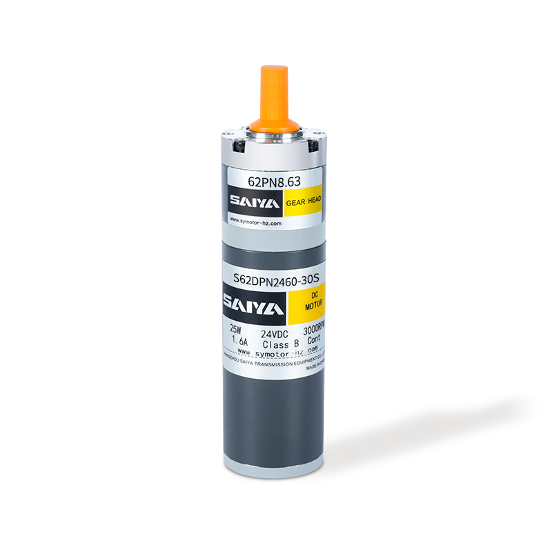
The 62mm brush planetary gear motor is a versatile and efficient component widely used in various applications requiring precise torque and speed control. With a rated current ranging from 2.5 to 5.5A...
See Details
CONTACT DETAILS
- TEL: 0086-0571-86951513/86951543
- Fax: 0086-571-86040769
- E-mail: [email protected] / [email protected] / [email protected]
- Office: Hangzhou Saiya Transmisson Equipment Co.,Ltd
- Office Address: Room 2201, Wanyin building, Hangzhou City, Zhejiang Province
- Factory: Zhejiang Saiya Intelligent Manufacturing Co., Ltd.
- Factory Address: No.35 Building , Zhongnan High-tech Yunhe Zhigu Industrial Park, Xinan town, Deqing county, Huzhou city, Zhejiang, China
QUICK LINK
PRODUCT
If You Are Intrested
In Our Products,
Please Consult Us
Copyright © Zhejiang Saiya Intelligent Manufacturing Co., Ltd. All Rights Reserved.
Custom Gear Reduction Motors Suppliers
